Leaching Reactor Volume Calculator from Residence Time
Residence time is the parameter most often traded away to raise throughput, and it is usually the wrong thing to trade. This calculator works the sizing in the practical direction: give it the slurry flow and the residence time your leach kinetics need, and it returns the total working volume, the volume per tank for the number of tanks you choose, and the physical dimensions for a stated height-to-diameter ratio.
Results
The results appear here and update as you type. Each result is followed by the conditions under which it holds.
How to use it
- Establish the kinetics, not the rule of thumb
Run a batch leach at your intended temperature, pulp density and lixiviant concentration, and plot extraction against time. The residence time you need is the point where the curve flattens towards your target — anything beyond it is reactor volume you have paid for but do not use.
- Convert flow and time into working volume
Working volume is slurry flow multiplied by residence time. This is the volume the slurry must actually occupy, and it is independent of how you divide it among vessels.
- Add freeboard to get geometric volume
Vessels need freeboard for aeration, foam, and surge during flow changes. Working fraction is the share of the vessel that is slurry at normal operating level.
- Choose the number of tanks in series
The same total volume split across several tanks in series behaves closer to plug flow, so recovery rises without spending more volume. It also costs more vessels, more agitators and more interconnecting pipework.
- Fix the aspect ratio and read off dimensions
Height-to-diameter ratio trades floor area against agitator shaft length and air requirements. A very tall, slender vessel is harder to agitate evenly and is more prone to solids settling in the base.
Formulas used
Total working volume  V = Q × (τ / 60)
Geometric volume      = V / (working fraction)
Volume per tank       = V / N                          N = tanks in series
For volume of one tank:  V_tank = π (D/2)² × (H/D × D)
   solve D = ( 4 V_tank / (π × (H/D)) )^(1/3) ,  H = D × (H/D)
Assumptions & applicability
- Ideal mixing within each tank, with tanks in series to model the residence time distribution. Real vessels have dead zones, short-circuiting and stagnant corners, so the effective volume is normally less than the geometric volume.
- The required residence time is an input that must come from batch leach kinetics on your own material. Leach rates vary by orders of magnitude with particle size, mineralogy, temperature and lixiviant strength, so a generic figure is not usable for design.
- Constant slurry density and flow. In reality pulp density changes along the circuit as solids dissolve and as wash water is added.
- No allowance is made for solids settling out in the vessel, for agitator power limits, or for the increase in viscosity and the fall in mixing quality at high pulp density.
- Heat input and temperature control are not modelled, although leach kinetics depend strongly on temperature.
- The scaling and abrasion behaviour of the vessel and agitator material is not considered.
FAQ
Why use several tanks in series instead of one large tank?
Because the total residence time is the same but the distribution is much narrower. Part of the slurry cannot short-circuit straight through, so more of it actually receives the full contact time. That translates into higher recovery for the same total volume, which is why leach circuits are almost always built as a series of agitated tanks rather than one large vessel.
What pulp density can I run?
The practical ceiling is usually set by mixing, not by chemistry. As pulp density rises, slurry viscosity rises sharply, the power needed to keep solids in suspension rises, and the driving force for dissolution falls because the liquid-to-solid ratio drops. Establish the achievable density in an agitated test vessel at your intended geometry before committing to a reactor design.
Should I use an agitated tank or a column or autoclave?
It depends on the kinetics and on why you are leaching. Atmospheric agitated tanks suit slow kinetics and coarse solids, autoclaves are needed when the chemistry requires elevated temperature and oxygen overpressure, and columns or heaps suit very low-grade material where long residence times are acceptable because the cost per tonne is low. The decision is normally made by kinetics together with the required oxygen or pressure, not by tank volume.
Terms used above
Equipment sized with this calculation
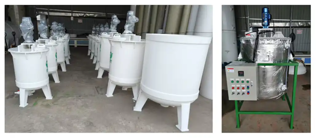
Pilot-Scale PP Reactor
9 Specifications · pp reactor
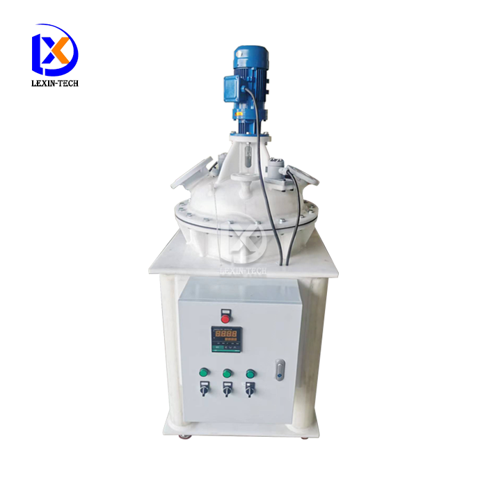
Lab-Scale PP Reactor
9 Specifications · pp reactor
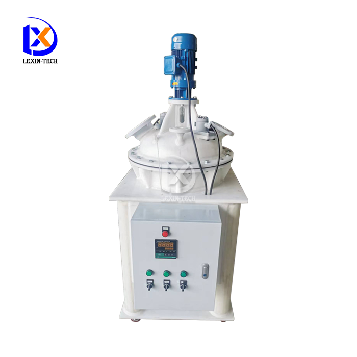
Electric Heating PP Reactor
8 Specifications · pp reactor
Further reading
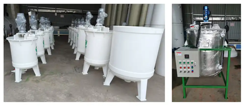 KBHow to scale up from Pilot-Scale PP Reactors?how-to-scale-up-from-pilot-scale-pp-reactors
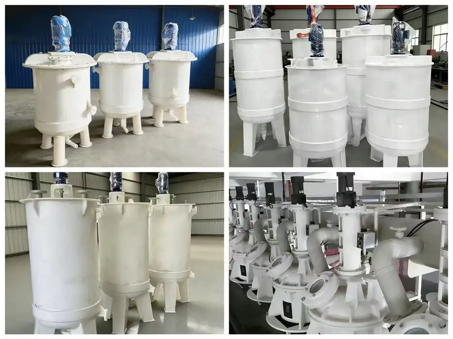 KBAlkali Resistant PP Reactor Stirring Systems and Agitation Typesalkali-resistant-pp-reactor-stirring-systems-and-agitation-types
Get this sized against your own material
The calculator returns a pre-feasibility number. For a quotation we need the feed assay, throughput, medium and temperature — and, where the result hinges on it, test data from your own material.
Request a sized quotation Ask an engineer a questionCalculator reference TL-LEACHING-REACTOR-RESIDENCE-TIME. This tool is provided for preliminary engineering estimates. Final equipment selection must be confirmed against test work on your own material and reviewed by a qualified process engineer.